Building the Filters
Based on the paper presented at the Karlsruhe Institute of Technology's Workshop on Software Radio (WSR).
The paper starts off by explaining how to build the prototype filters and how these lead directly to the concept of the polyphase aspect of the filterbank.
Running scripts from this tutorial requires a GNU Radio version compatible with 3.7.3 with gr-qtgui.
Also, things were changing a bit while working on the paper, and so some of the numbers there might be off a bit. When in doubt, use the numbers in the scripts provided in this post. If they don't work perfectly for you, you can always play around with them.
If you run this script, it uses GNU Radio's firdes program to build a low pass filter than can be used for a 4 channel channelizer. It then plots the original prototype filter as a set of taps as well as the individual filters as they are partitioned among the four channels, as shown below. The trick here is to realized that a) the partitioned filters are down-sampled versions of the original filter and b) each version is the same filter at a different phase (at 2pi m / M). So the prototype is built at the highest sample rate of the filter but designed for the channel bandwidth of the baseband channels.
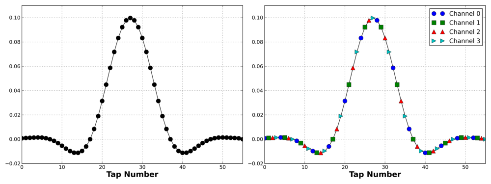
The code to generate this filter is:
lpf = filter.firdes.low_pass_2(1, 1, 0.05, 0.05, 60)
We use a 4 channel example here to make the visualization of the filter taps easy. But a more interesting channelization problem is do handle bigger sets of channels. Because it's easy and available, I'm using the FM broadcast band from 88 to 108 MHz. Each channel is 200 kHz wide, so there are 100 channels in the 20 MHz bandwidth. What would that filter look like?
Well, we can play around the parameters quite a bit to give us our desired performance. I'm going to intentionally introduce some slack to the filter with the knowledge rarely will we see two FM stations right next to each other in frequency. So I can go outside the channel bandwidth a bit so as to make a much cheaper filter. In this case, we use the parameters:
- Type: FIR
- Style: Low Pass
- Window: Hann
- Sample Rate: 20 MHz
- Filter Gain: 1
- End of Pass Band: 125 kHz
- Start of Stop Band: 225 kHz
- Stop Band Atten: 60 dB
The filter can be easily constructed and visualized using our gr_filter_design tool that comes installed with GNU Radio.
This builds a filter with 545 taps, which sounds like a lot. But we're constructing a filter that has a transition band of 100 kHz at a sample rate of 20 Msps, so what were we expecting? Luckily, however, the filterbank partitioning breaks this into 100 equal length filters, which means that each filter only has ceil(545/100) = 6 taps in it. Which sounds a lot better.
Channelizer
We can now use this filter two ways. First, let's use the PFB decimator (pfb_decimator_ccf) block. This, in its normal state, it just the normal fir_filter_ccf block of GNU Radio. But it has one extra parameter that allows us to take out the specified channel we are after whereas the normal FIR filter can only produce the baseband channel (channel 0 in our terms).
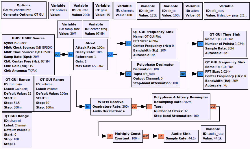
Using this GRC flowgraph, we take in samples from a radio. For this example, we have it set up as a UHD device and one that can specifically support 20 MHz of bandwidth. Mine on the desk in front of me is a USRP N210. We are then taking the wideband input channel and passing it to the PFB decimator with our given taps as shown above. The decimator's channel is actually a user-selected value during runtime, so we can very quickly move from one channel to another with the click of a mouse button. With this flowgraph, we can see the original full FM spectrum and the spectrum and time series of the selected channel.
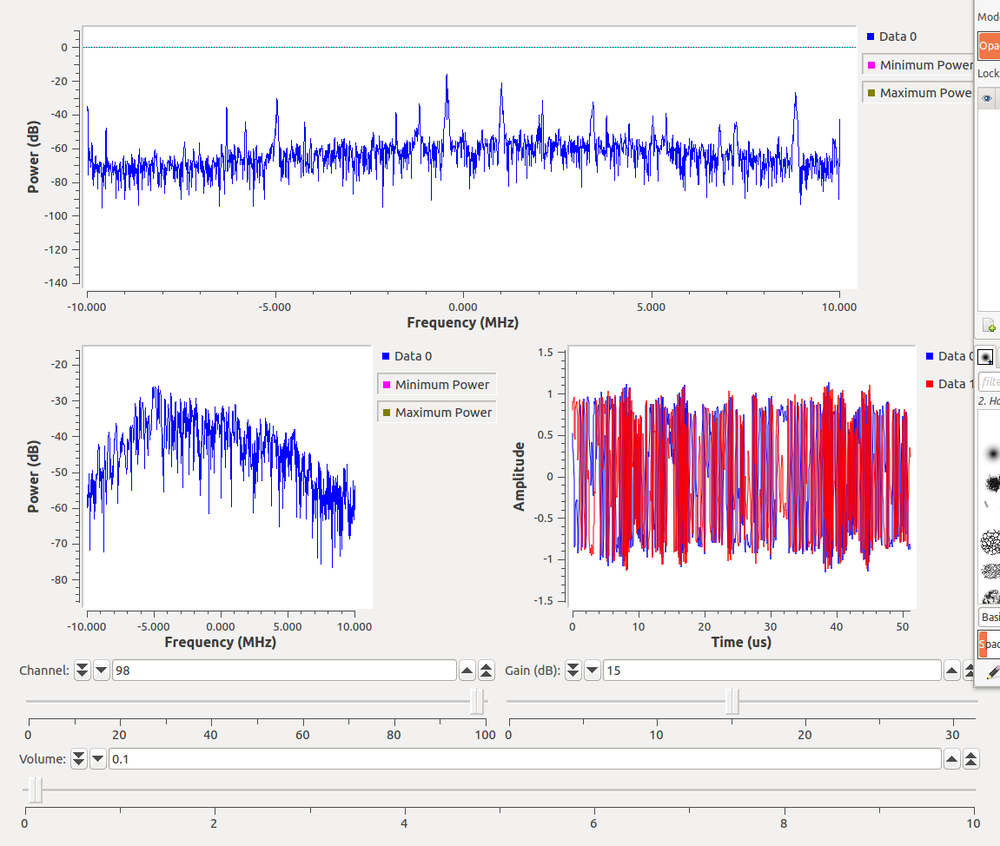
And here's a resulting channelized FM station out of the flowgraph:
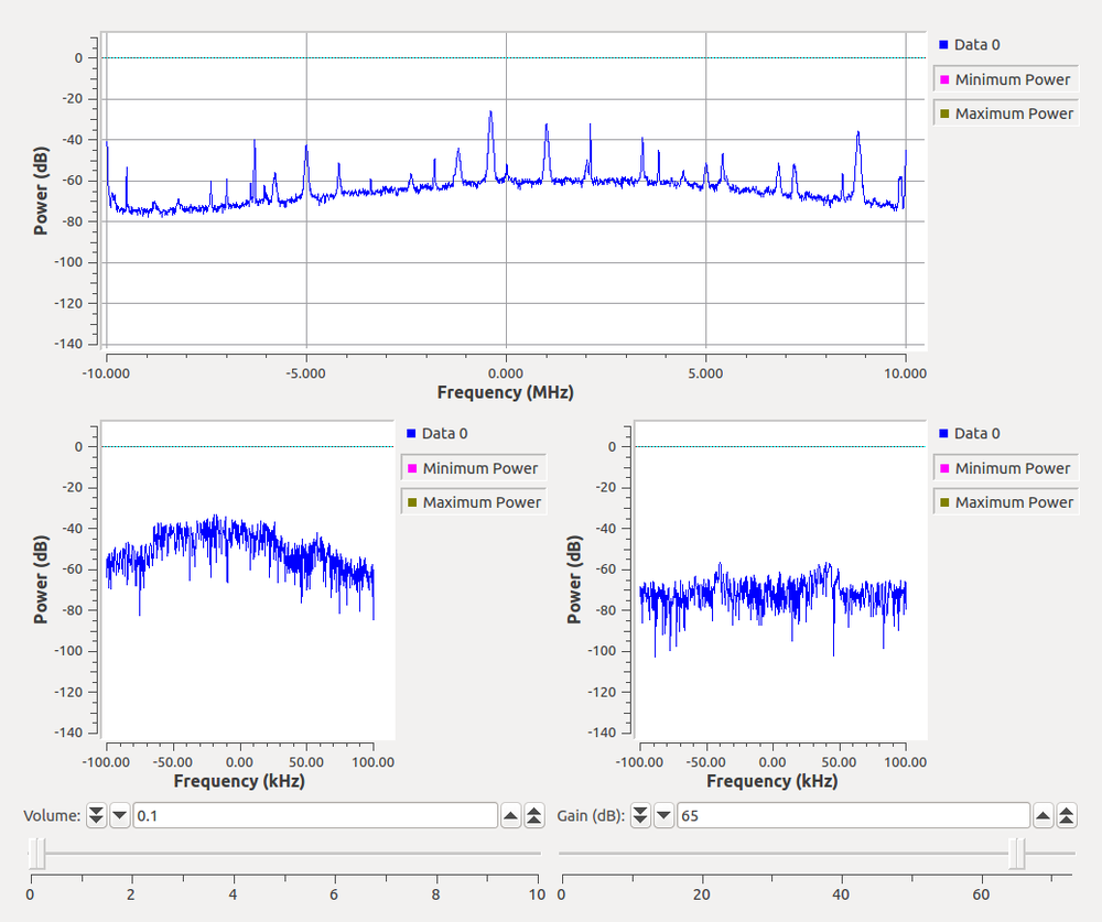
We can also use this script that uses the channelizer to pull apart all channels at the same time.

Here, we're only showing two channels instead of all of them. But we could selectively pull out any channels we might want for the rest of the processing. The output of this looks like:
Just a word of caution. While the channelizer is fairly computationally efficient, we are still talking about working with 20 MHz, so you'll be using quite a bit of compute power, regardless. So don't be too surprised if you run into CPU limitations.
Synthesis Fitlerbanks
The synthesis filterbank is the reverse of the channelizer (also known as an analysis filterbank). It takes in multiple baseband channels and produces a single wideband spectrum. We'll use a very simple example to work through the basics of this. We'll just take four sine waves at different frequencies and synthesize them together.
First, we have to have some understanding about what the synthesizer does for us. In the digital domain, we can simply take in four signals and synthesize them on to four channels. But, what this turns in to is a situation where we are splitting channel 2 around the edge of the spectrum. Basically, the channel layout of the wideband spectrum looks like:
| 2 | 3 | 0 | 1 | 2 |
Channel 0 is the channel around DC (or 0 Hz), so because we are using an even number of channels, we split one channel around the fs/2 boundary. At complex baseband, this is fine, but we obviously wouldn't want to transmit this way. So the PFB synthesizer allows us to have more channels that we actually want to use. For this scenario, let's use six channels for the four signals. That way, we have the mapping:
| 3 | 4 | 5 | 0 | 1 | 2 | 3 |
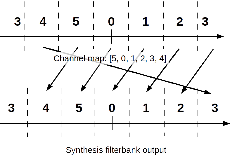
Next we have the problem that if we insert four signals into the synthesizer, how do we tell it which output channels to use? By default, it will use channels 0 - 3, which leaves us with the same problem as before. The synthesis block has the ability to set the channel map, which changes the input stream to output channel accordingly. The map basically says that the channel on index x will output to channel channel_map[x]. The following figure might help explain it better.
The flowgraph looks like the following. The original signals have frequencies of 10 kHz, -10 kHz, 20 kHz, and -20 kHz with a baseband sampling rate of 100 ksps. We use the channel map [5, 0, 1, 2, 3, 4] to left shift each channel once so that we avoid using channels 3 and 4.
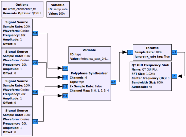
We expect the output to be at 600 ksps with sine tones at -90 kHz (the original 10 kHz), -10 kHz (originally -10 kHz), 120 kHz (originally 20 kHz), and 180 kHz (originally -20 kHz). The PFB synthesis filterbank's prototype filter was constructed using the following:
firdes.low_pass_2(6, 6*samp_rate, samp_rate/3.0, samp_rate/4.0, 60)
The filter, again, is designed at the high sampling rate, which is the output sampling rate of the synthesizer. The bandwidth is a bit less than the channel bandwidth with a bit of a roll-off. The output looks like:
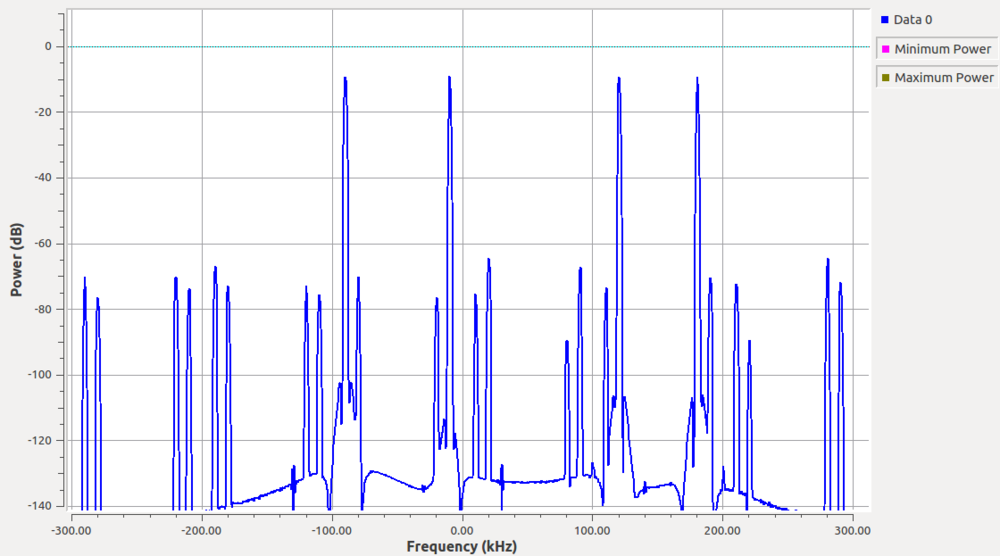
We can see the signals as the four peaks positioned exactly where we expected them to be. The other spikes throughout the spectrum are the result of synthesis process and aliasing of the channels, but notice that each is suppressed by about 60 dB or more from our peak signals. This is due to the fact that our out-of-band attenuation specification of the prototype filter was 60 dB. If more suppression is needed, we can make a more complex filter.
Reconstruction
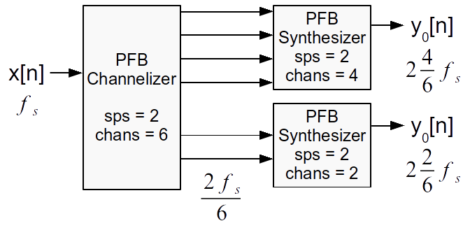
We'll end by going over the reconstruction filter. You can see in the paper the different steps of building up the filterbanks and how to analyze the reconstruction filters. The first case takes ten channels and fuses the results together while the second case takes six channels and recombines two and four of them as different outputs. You can download the Python scripts linked in the last sentence to look at how these behave. The following figure shows a diagram explaining the two output script.
The impulse scripts above are just good tools to understand how perfect our reconstruction is. The real trick to designing the reconstruction filters is to make sure that the end of the passband at -6 dB is at exactly the channel spacing and that the transition of the filter is set appropriately. Using the GNU Radio firdes, we can do this exactly and easily. The end of passband parameter we pass to our firdes filter designers specified where that -6 dB point will be, so we set that to half the channel's baseband sample rate. Using a Blackman-harris window with a stop band attenuation of 80 dB, the transition band should then be set to the baseband sample rate divided by 5. We're not quite sure, yet, why this number works, but Sylvain Munaut discovered this works universally for any sample rate while at our KIT hackfest last week. So given that fs is the baseband channel sampling rate, we can construct our filter as:
firdes.low_pass_2(1, M*fs, fs/2, fs/5, 80, firdes.WIN_BLACKMAN_HARRIS)
But the real result in the paper comes from taking an FM channel and splitting it into multiple channels and then reconstructing them again. We have the following flowgraph for this. You might have to change some settings on your UHD device to get it to work properly.
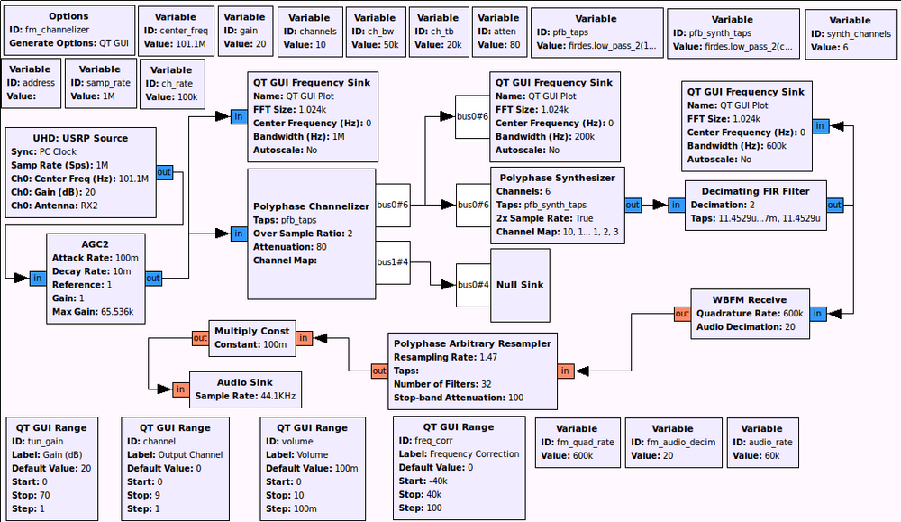
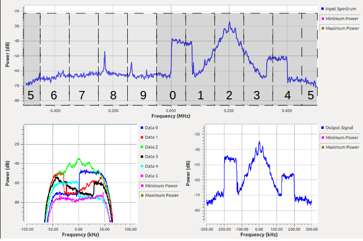
The result will look something like this, where the output of the synthesis filterbank is an FM signal centered at baseband that can then be demodulated like normal. This figure was edited to describe the channels, how the original signal was channelized, and which channels were synthesized to reconstruct it.
I hope this walk-through of different uses of the channelizer and synthesis filterbanks helps make them a bit easier to use. Specifically, the prototype filter tends to be the hard part, but once the basics of it are understood, I expect that translating it to other needs shouldn't be terribly difficult for most people.
One thing that comes up with this study is our use of the firdes filter design tool, which uses windowed sinc functions. These tend not to be the most optimal, but I like them here because they are easy to design and control. Especially for our reconstruction filterbank work. Other filter design tools can be used, possibly more effectively, so there is nothing stopping anyone from designing their own filter however they like. The same principles of design and application will work.
